Detail Work

Had a small window to make some progress on the toy kitchen, so took that time to rout some 3D carving (with the 3D Router Carver friom Carb-i-tool) into the side panels before assembly.

These were much more popular before CNC machines were readily commercially available.  Strangely though, most workshops don’t have CNC available, so it is a bit surprising that sales of the 3D carver have so diminished.

I find these are pretty easy to do, and a typical pattern takes me about 10-15 minutes.

3D Carver template in place

3D Carver template in place

As the router bit is mounted with a large cone, as the width of the template opening increases, the depth of the router carving goes deeper.

Completed carving

Completed carving

This was the deer profile which I hadn’t used before, but worked very well.

I also had carved a puma, an eagle and a horse.

Puma

Puma

So the final result is each end will be different from one another.  I then glued up each rail & stile, with raised panel, clamped up with the Bessey clamps purchased earlier in the year (I could really do with more of those!)

Next step is to complete the carcasses, and put some flesh on the bones of the units.  Once that is done, it is a matter of adding the details that will set the project apart, and the more, the merrier.

Hopefully it will all come together pretty quickly – I am feeling a bit of time pressure, not only because of it now being December (?!), but the added burden of the house/shed relocation (and the inevitable preparation of the current place, which will be a lot of work, and also has to be done during all the free time I have between now and Christmas!)  Best I knock this project over very quickly!


Skirting the Edge of Boxmaking

I’ve been intending to get more into some of the classic projects, and time always seems to be against me, but finally got a window of opportunity to start a quick box for Xmas.

Still plenty of steps to go (did the glue-up this evening), so it is progressing at least.

Dovetailed Sides

Dovetailed Sides

The sides have all been (machine) dovetailed. (Ie, using the router table rather than cutting them by hand – leaving that for another day!)  The outside of the box is yet to be sanded, let alone have any finish applied.

The dovetails were cut with the Gifkins Dovetail Jig – a very quick, and successful method for firing out full dovetails. A slot was cut around both the top and bottom of the box.  The lower slot is for the base, with a rebated edge to fit neatly into the slot and sit flush with the table.  In this case, there is also an upper slot which is for a sliding lid.

Lid Assembly

Lid Assembly

The lid is made with a slot all round, both for the tongue and groove joint for the frame, as well as the floating raised panel.  The raised panel was made using a rounding panel bit on top, and a rebate cut on the bottom.

Not much to look at currently – will have some more photos during the finishing phase of the box.

Unorthodox Triton Router Table Mod Part 1

I’ve had a few queries about my unusual table top in my recent post about Router Tables. So to cause a bit of controversy, here is the article I wrote at the time about the modification. To clarify however, I still use an original, unmodified Triton Router Table quite successfully, so this is another one of those “I’ll always try to modify everything kind of thing!”

**************************************************************************************

I have been using the Triton Router Table for a few years now (with the Triton Router pretty much permanently mounted), and have found it to be an excellent way of performing most router operations. In fact, other than some totally unavoidable operations where I need to do freehand routing, I wouldn’t dream of not using a router table. As things have progressed, I have been expecting more and more from my equipment, in their capabilities, and accuracies, and have been reaching a point where I needed to use bigger and bigger router bits, and/or a very high degree of accuracy. As I have written in another article, (which I’ll post here soon) the micro-adjusters for the Triton Router Table are excellent for achieving precise fence movements.

When using some very large router bits (such as for raised panel joints), I found that the Router Template Guide plate got in the way, so I wasn’t able to lower the bit far enough to achieve the cut that I wanted. To get around this, I had three options. The first was really not an option at all (lowering the router). The second was raising the work, which although ok, made it difficult to achieve the same setup every time (you don’t want each door on a raised panel cabinet looking different!) The final solution was to make the Triton Router Table top thicker. This had an added benefit of allowing a 1-piece top, which meant that there was no chance for the front edge of a piece of work to catch the top of the table at all, or worse, experience any dip or rise as it progressed past the router bit.

Photo 1 – Original Triton Router Table

There were a few things that I demanded of the upgrade.
1. Retain the ability to use the fence, perform through-table bit changing, and still be able to use the various router table jigs (finger joiner, biscuit joiner, jigsaw table).

2. The modification must be fully reversible, which adds an extra dimension to the design.

3. The table must still be able to take a full range of bit sizes, from the 3mm Triton bit, through to panel making bits, without ending up with a huge cavity when using the smaller bits.

4. Safety must not be compromised.
My solution was to attach a new single piece of aluminium sheet over the entire tabletop, while still leaving the slot for the sliding portion uncovered, and therefore usable as originally intended. After much thought, I finally clicked to the best way to do this- attach the new top to the removable router holding plate, so that it gets removed at the same time as the router is.

Click here to read full article

Router bit of-the-month (January)

The router bit-of-the-month featured in Episode 19 is a raised panel bit from Carb-i-tool and has their typical quality features: low friction coating, high quality carbide, anti-kickback design and importantly, accurate dimensioning of the shaft. I have quite a few Carb-i-tool bits, as you may have gathered from other posts, and I always have a great deal of respect for the quality of the bits (and the subsequent quality in finish they produce), as well as the (for me) very important fact that it is a local manufacturer turning out such a good product.

There are a number of profiles available for the raised panel, it is a matter of choosing which one you feel suits the product you are making (and one that complements the rail and stile profile). This cutter is a horizontal style cutter, as opposed to a vertical raised panel bit. In other words, the panel you are routing is presented to the cutter horizontally, ie resting on the router table. I tend to prefer this type of bit, as it means the workpiece is fully supported by the router table, and I don’t have to balance the panel against the router fence. This is particularly important for large panels. So that is the positive aspect, and I feel this is the preferred orientation. However, it does mean the router bit itself has to be huge (and the raised panel bit is often the largest router bit you’d ever own). It is a huge chunk of steel and carbide that the router needs to spin, and as such, you need a strong, heavy duty router to cope with it, and essentially, one that is variable speed. (Check a post I made recently about matching router bit speed to the size of the bit).

If your router cannot cope with such a large bit, then the vertical raised panel bit is the way to go, as it is nowhere near as large a diameter bit, and the router can cope with it much easier. You do need a good, high fence to support the panel then, so that is the compromise.

I tend to use an unbearinged raised panel bit, as it leaves my options open for exactly where I position the fence, and I can centre the fence on the bit, or have it as far forward as I’d like. If the bit had a bearing, I would be limited to just how much of the profile I could expose with the fence. In any respect, I am always going to use a fence with this bit (and a router table). It is way too large to ever consider handholding the router.

Also, given the amount of material this bit can remove, it is highly advisable to take multiple passes to remove all the material. You can achieve this in 2 ways. Either by moving the fence, starting with only a little of the cutter exposed, then expose more for the second pass, then set the fence close to the final position for a third pass and finally set it for the full depth pass so that one is a very light pass (ie removing very little material) which really improves the quality.

The other method is to set the fence in the final position to start, then raise the router bit each time instead, until it is at the correct depth for the final pass. For some reason this is my preferred method, but either is perfectly valid. Both have the problem that if you want to produce another panel later, you need to reposition the fence and the bit depth exactly, so obviously, ideally, you’d have all the panels ready to go, and do the same pass on all the panels one after another before changing bit depth (or fence position), so each panel is at the same stage when you set up for the final pass. It is worthwhile also running a bit of scrap wood through the process at the same time, so that you can set it aside, and use it to help reset up the fence and bit depth if you ever do need to produce another matching panel at a future date.

Episode 19 Router Bit Review Raised Panel Bit

Raised Panel Bit. To complement the rail and stile bit featured last month, the raised panel bit is used to produce the panel that fits into the frame created by the rail and stile. The result is a very traditionally styled raised panel, used for cupboard doors, drawer fronts, and even the sides of some types of furniture.

Progress!

(Finally) was out at the shed a couple of days ago, getting some new footage for the next video, which I may even have finished by tomorrow (hopefully). It is a look at the raised panel router bit, and was my first chance to try out the new Incra Wonderfence that I have just fitted.

I don’t think that I can claim that there was any real difference (for this operation) between the old fence and the new, although I was able to fine-tune the outfeed fence very precisely, and it is that degree of control that you are really paying for with that fence system.

I always say that you can never really claim to own something until you have at least taken it apart and reassembled it, and ideally made some modifications, and even here I did a minor tweak of the fence. I was getting a tiny catch as the material was running onto the outfeed fence (despite being as inline as I could get it), so I have taken a bastard file and just put a slight radius on the leading edge of the outfeed fence. That helped dramatically, and solved one of my pet hates (and the very dangerous situation) of having your work get a hangup (ie getting stuck) partway through a cut.

When I have a little more time, I will make up some zero-clearance panels to use with the Wonderfence, and that will improve the situation even further.

The Router Fence Upgraded!

It has been a while coming…

When I first purchased the LS Positioner, I gave a lot of thought to whether I could justify getting the Incra fence, or whether I could construct one as functional, and a lot cheaper. I decided to try, and the fence I came up with I am pretty happy with.

pict5778.jpg

It has UHMD plastic on its face, which can either be positioned to close near to the bit, or with a small central piece to act as a zero-clearance fence (ie, the opening in the fence has no gap around the bit, virtually eliminating any possibility of the workpiece getting hung up (ie catching) on the outfeed fence). There is a track on the front for a right-angle fixture, or a featherboard, and another on top for a stop. There are 2 rails of positioning track, one metric, the other imperial, and a movable rule.

However, there have been a few issues with it. Firstly, I never finished it- like the base of the table, it got put aside as more pressing things cropped up, and I haven’t returned to it. There wasn’t much else to do – dust extraction, feather board, and the stops themselves. I haven’t been completely happy with the zero-clearance design, and have since thought of better ways of doing it. The other issue, and more difficult to add, is the ability to offset the infeed and outfeed fences. This is critical for planing type operations (such as using the compression bit covered mid last year). It was a feature that I had on the Triton Router Table, but have missed being able to do it easily. I don’t use it all the time which is why I’ve been able to get around not having it. Finally, I never perfected a right-angle fixture. I did get a home-made one from a friend (Steve Bisson, who sadly passed away mid last year), after he upgraded his system to the full Incra one (and was the final inspiration that convinced me the Incra system was unique in its accuracy, and therefore versatility).

I have always regretted not biting the bullet in the first place, and getting the whole system, including the Incra Wonder Fence, so finally, the deed is done.

Here is the fence as it is tonight.

pict5779.jpg

It sure looks the part now! The fence halves are actually mounted on a length of Incra sawtable fence that I had, and I’ve included the high-riser (the black bit on top), which helps stabilise tall boards passing over the bit (such as a vertical panel-raising bit). I also (finally!) have the proper right-angle fixture which will make the various joints (dovetails in particular) much easier to complete.

pict5780.jpg

One thing that the Wonder fence does give, is very precise control over the offset between the infeed and outfeed fences. You can’t see it very clearly in the photo, but it means the offset is very easy to produce.

All the Incra gear seen here was sourced from Professional Woodworker Supplies.

Episode 18 Router Bit Review Rail and Stile Stacked Bit

Stacked Rail and Stile Router Bit. As discussed very recently on Stu’s Shed, this is a very impressive router bit, and has sold me on the concept of stacked rail and stile bits, rather than having two separate matched bits to perform the same job.

Router bit of-the-month (December)

The router bit for December is the Carb-i-tool Stacked Rail & Stile Bit (which will be featured in a Video Episode very shortly).

railstile.jpg

This router bit is unusual from the standard method of cutting rails and stiles, as normally that is performed with two separate bits. In this case, common elements are used for both cutters (which does decrease cost), and makes the transition between the two tasks incredibly easy.  This router bit is designed solely for use in a router table, and works much better when the workpiece is being supported by the router table fence.

pict5584.jpg

This is a typical rail and stile joint (and was produced with this cutter). As you can see, the Roman Ogee pattern continues around the interior of the frame, including right into the corner (shown). Anyone attempting to do this simply by first gluing up the frame, then running a bearinged bit around would have discovered that it isn’t possible to get into the corner like this. Secondly, the joint itself would have been a simple butt joint, and therefore would likely require reinforcing (such as a biscuit, spline, pockethole, dowel, domino etc).

Also, notice the slot that has been cut – this is to fit either a raised panel (which will be subject of the next router bit review), or a flat panel (such as plywood, glass, perspex etc).

So what makes a rail and stile different? The secret is how it is assembled. The stiles (the vertical members) are cut, with the pattern (such as the Roman Ogee) running their full length, with no attempt to stop the bit breaking out either end. The rails are cut the same way, but then their ends are given a second treatment, where the reverse of the pattern is cut into them so they fit precisely into the stiles.

pict5585.jpg

In this image, we can see the end of the stile (on the left), and the rail with the reverse pattern cut so it matches in exactly into the stile. This also gives a significant increase in the amount of glue-area, making for a strong joint (well certainly a lot stronger than a simple butt joint!)

pict5586.jpg

This is step one – the primary pattern is cut the length of all the rails and the stiles. The workpiece is placed face-down on the table for this cutter, and the depth of cut is controlled by the bearing.

pict5587.jpg

Next, the rails are turned up the other way, and presented to the upper portion of the cutter, so that the channel cut in step one matches precisely with the bearing (and fits in between the two cutters). Only the end-grain is cut in this step. To line the piece up with the upper portion of the cutter, you can either drop the cutter further down into the table, or (funnily enough) raise the workpiece up to the required height. I decided that this was the better way to go, as it means that I don’t have to play around realigning the cutter every time that I want to make another (door, cupboard side etc). So I came up with this jig:

pict5491.jpg

Ok, it does look a bit weird (like a child’s aeroplane), but there is good reason.

The baseplate has been thicknessed very carefully to raise the workpiece up just the right amount so the top cutters will cut the rails’ end grain perfectly.  The thickness of this baseplate has to be matched to the thickness of the stock, so in this case I can only use this jig for 19mm stock.  On top of that are two lengths that the rail passes between.  They need to be exactly 90 degrees to the ‘wing’ which means the rail is also held exactly perpendicular to the fence.  Their ends are sacrificial, and provide tear-out support to the rail as it is being cut. The ‘wing’ runs along the fence, and is high enough to pass completely over the top of the cutter without touching.  It is quite long so as to provide plenty of support before and after the router bit so there is little chance the jig can twist during use.

pict5492.jpg

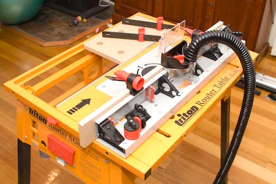
Here you can see the jig in position, ready for the rail to be inserted into the slot, then the whole unit can be run past the router bit.

pict5589.jpg

Finally, here is the resulting cut – you can see the end of the rail that has just had its end-grain machined.   The jig certainly makes the task very easy, and very repeatable.  You would not dream of trying to cut the end-grain without the workpiece having some form of support (such as a mitre gauge)…..unless you like having workpieces thrown around the workshop, and possibly pulling your hand into the cutter……

So my verdict: I am a big fan of Carb-i-tool bits, and this one is no exception.  I am sold on the whole idea of stacked rail and stile bits – I have a couple of sets of the matched pair type, so an quite familiar with setting them up, changing bits during the job to make the rail ends, needing to make another and having to set the first up again etc etc, and having it all in one bit definitely works.  The jig works as well as I could have hoped too btw.  So if you are wanting to do some rail and stile work, this is definitely a bit worth looking at.  There are different profiles of course, simple roundover, Roman Ogee, Classic etc

As I mentioned, there is a video coming very shortly on the topic, and the matching panel will be the subject of next month’s router bit of-the-month.

Woodwork 101 – Router Bit Speeds

A question that comes up on a regular basis, is how fast do I have the router for the different bits?

Obviously, this is only really applicable for variable speed routers. It doesn’t mean that the information here is not applicable for fixed speed routers, but instead indicates at what point (ie at what bit-size) that the fixed speed router should not be used.

What we are really concerned with is the tip speed – ie the speed at the outside edge of the bit.

For example, we have 2 bits – one 80mm diameter (approx 3″) (a panel raising bit), and a 13mm bit (approx 1/2″) (a straight cutter). Our router is set at 22,000RPM.

The tip speed of our 13mm bit will be around 54km/hr (33mph). Whereas our 80mm bit has a tip speed of 330km/hr (206mph).

The large bit is therefore running way too fast for optimum performance and safety. However, it is not a matter of running every bit at dead-slow. A router after all is a high rotary speed tool – the bits are meant to run fast. If you run too slow, you risk chatter, kickback, and tearout. If you run too fast, you risk burning of the wood, and catastrophic failure of the bit.

Here are some suggested (maximum) router speeds, which can be used as a starting point for determining the optimum bit speed. Now unlike any other table that I’ve seen for router bit speeds, mine gives plenty of overlap. This is because I have researched the various recommendations out there and the general consensus seems to lead to a suggested tip speed of 100 – 150 km/hr. If you are uncomfortable with higher speeds, or are going to make a heavier pass, removing large amounts of material, then tend towards the lower end of the scale. For final passes removing very little material, tend towards the upper range.

I have also based them around a router with a speed range of 8000 – 22000 RPM.

00mm – 35mm: 22000 RPM
20mm – 40mm: 20000 RPM
30mm – 45mm: 18000 RPM
35mm – 50mm: 16000 RPM
40mm – 60mm: 14000 RPM
45mm – 70mm: 12000 RPM
55mm – 80mm: 10000 RPM
65mm – 90mm: 8000 RPM

Determining the final speed also needs a few other things to be taken into consideration. Sharpness of the bit, quality of the bit, quality of the router (the bearings, and the collet), density of the material being routed, and material feed rate. (I refer to material here, rather than just wood, as it is feasible to use a router on some metals (such as aluminium), and plastics. However, I am not covering the other issues involved in routing different materials. Even wood has a phenomenal range in material characteristics that I can’t take into account here.)

It is generally a very good idea to make test cuts until you are familiar with the working properties of the material.

Another point is how much material to remove in any one pass. A straight 1/2″ cutter can generally handle a single pass (in softer material such as pine), but taking 2 passes leaves a better finish, and places less load on the router and the bit. In some instances (such as dovetails), multiple passes with the same bit isn’t possible, but even then, you can use a small straight cutter to remove the bulk of the material before switching in the final bit.

For something like a panel raising bit (80-90mm diameter), you may think that running it dead slow and going in one pass is the answer (with a slow feed rate). It isn’t though. The tip speed may be high (150km/hr at 8000RPM), but the centre of the bit is only running at 15km/hr – not enough for a good finish (and never mind the huge load placed on router and bit removing all that material in a single pass). The only answer then, is multiple passes (or removing some of the bulk material on the tablesaw or bandsaw).

A final hint? Listen to the bit – it sound ‘funny’ when at the wrong speed. You get used to the sound that a correctly set router bit makes.

Oh, and one last thing. Any bit over 50mm is a router table job only. Even smaller bits benefit significantly by being used in this manner. Sometimes handheld is the only way, but if I have a choice, I use the router table every time.